How to Build a Simple 7.2V Battery Charger in 7 Easy Steps
When you’re tinkering with gadgets or restoring vintage electronics, a reliable 7.2‑volt charger can save the day. A DIY 7.2V battery charger lets you power NiMH, NiCd, or Li‑ion cells without buying a pricey commercial unit. Below you’ll find a straightforward guide that covers the right parts, safety tips, and the exact wiring steps to get a clean, consistent charge for your 7.2‑volt packs.
What You Need for a DIY 7.2V Battery Charger
- 2 × 3.6V NiMH or Li‑ion cells (or a 7.2 V NiMH pack)
- DC power supply (10 V–12 V, 1 A output)
- LM317 adjustable voltage regulator (or a 7805 variant with a drop‑in resistor)
- Current‑limiting resistor (≈ 1 Ω, 5 W)
- Heat sink for the regulator
- Diode (1N4007) and capacitor (0.1 µF) for smoothing
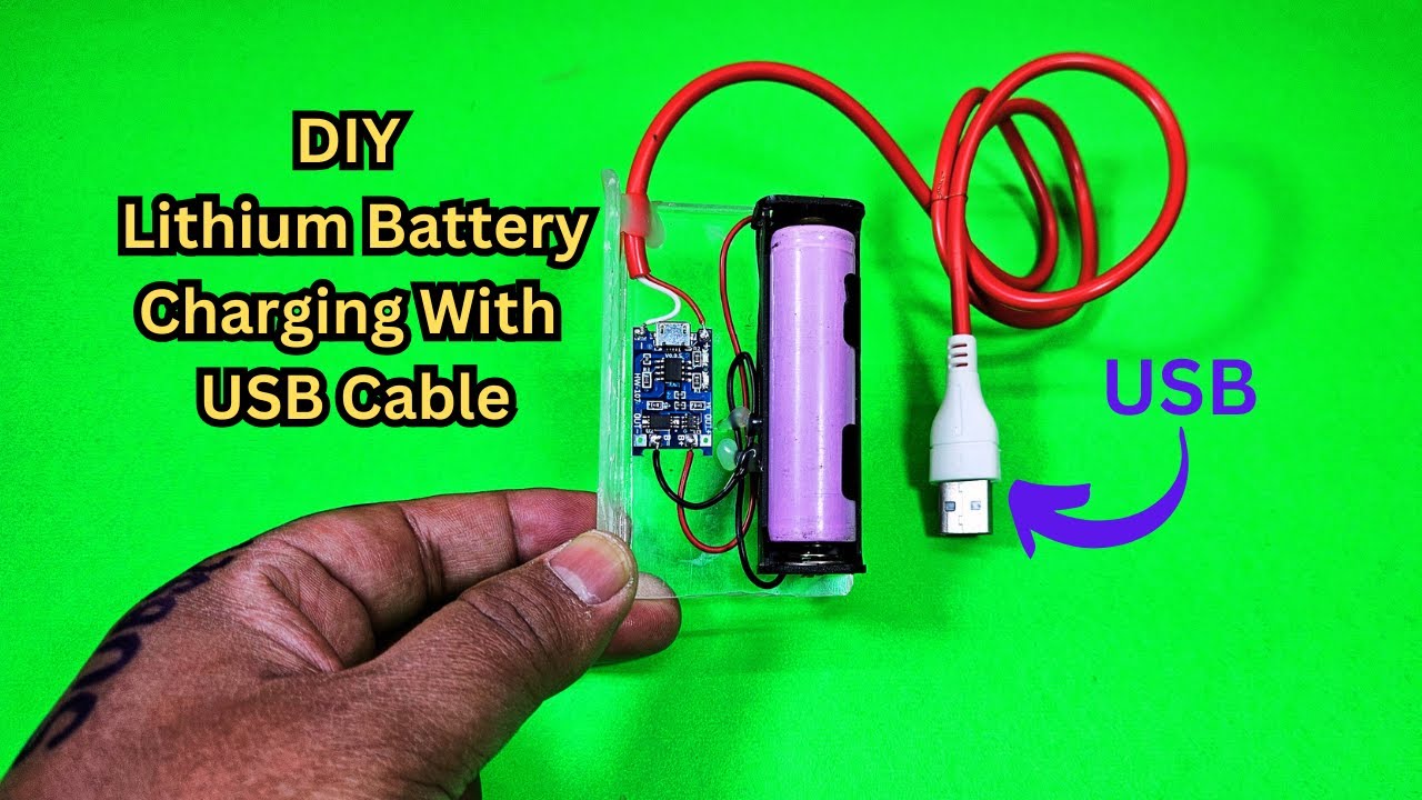
- Switch, fuses, and a 5 V USB port (optional for monitoring)
- Perf board, wiring, and soldering supplies
These parts are inexpensive and readily available at most electronics stores. Using a DC adapter that can supply a bit more voltage than 7.2 V ensures the regulator can produce a stable output.
Understanding 7.2‑Volt Battery Specs
Most 7.2‑volt packs are either a series of three 2.4 V NiMH cells or two 3.6 V cells wired in series. The total capacity is the sum of individual cells, while the nominal voltage is the series sum. When designing a charger, you must match the output voltage and limit the charging current to avoid overheating or overcharging.
Step 1 – Gather Components
Start by assembling everything on a small workbench. Keep your tools handy: a soldering iron, a multimeter, and a heat‑sinking station. Verify the DC adapter’s output with your multimeter before proceeding; a mis‑rated adapter will compromise the entire circuit.
Step 2 – Set Up the Power Supply
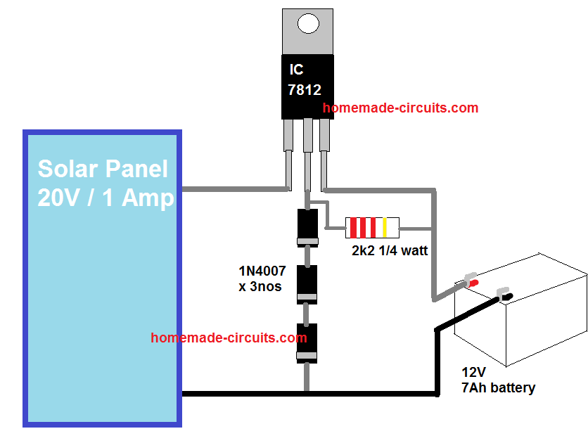
Connect the DC adapter’s positive lead to the input of the LM317 regulator. Place a 0.1 µF ceramic capacitor close to the regulator’s input pin to filter out noise. Ground the adapter’s negative to the regulator’s ground pin.
Step 3 – Wire the Charger Circuit
Attach the LM317’s adjust pin to the resistor network that will set the output to 7.2 V. Use the standard formula: Vout = 1.25 V × (1 + R2/R1) + Iadj × R2. Choose R1 = 240 Ω and calculate R2 accordingly. Solder the resistor network carefully to avoid short circuits.
Step 4 – Add a Current‑Limiting Circuit
Insert the 1 Ω, 5 W resistor in series with the charger output. This resistor will drop excess voltage, preventing the cells from drawing more current than the regulator can safely provide. The resistor’s power rating is calculated by P = I² × R; a 1 Ω resistor at 0.5 A dissipates 0.25 W, so a 5 W rating is generous.
Step 5 – Install a Voltage Regulator
Mount the LM317 on a heat sink; it can run hot under load. Connect the regulator’s output to the charger output line that goes to your battery pack. Use a diode in series to block reverse current from the cells back to the regulator, safeguarding both.
Step 6 – Build the Safety Features
Insert a fuse (1 A, fast‑blow) on the input side of the regulator. Add a small switch to allow manual shutdown. For added protection, incorporate a 5 V USB port with a voltage monitor if you plan to integrate a small LED or LCD for charge status.
Step 7 – Test and Calibrate
With the battery disconnected, use a multimeter to confirm the output is exactly 7.2 V. Then connect a dummy load (a resistor of the same wattage as your battery’s rating) and verify the current does not exceed 0.5 A. Finally, attach the actual battery pack and observe the charging curve; a gentle rise to full voltage over several hours indicates the charger is functioning properly.
Frequently Asked Questions
Q1: Can I use a standard 5 V USB charger instead of a 10 V adapter?
A1: No. A 5 V supply does not provide enough voltage to raise the output above 7.2 V after regulator dropout. Use at least a 10 V supply.
Q2: Is the current‑limiting resistor necessary?
A2: It protects the regulator from overheating and keeps the charging current within safe limits, especially when using a power supply that can deliver higher current than the regulator can handle.
Q3: How do I know when the battery is fully charged?
A3: A simple approach is to monitor the voltage; once it plateaus at about 8.4 V for NiMH or 4.2 V per 3.6 V cell in Li‑ion packs, the charge is complete. Alternatively, add a basic voltage‑monitor circuit to switch the charger off automatically.
Q4: Can I adapt this charger for a 12 V battery pack?
A4: The regulator and resistor values would need to be recalculated for the higher voltage, and you would need a supply capable of delivering at least 13–14 V to compensate for regulator dropout.